Electric glow discharge is a type of plasma formed by passing a current at 100 V to several kV through a gas, usually argon or another noble gas. It is found in products such as fluorescent lights and plasma-screen televisions, and is used in plasma physics and analytical chemistry, and has been proposed as an alternative method by which stars produce their visible spectra.[1]
The glow discharge owes its name to the fact that plasma is luminous, the luminosity is produced because the electrons gain sufficient energy to generate visible light by excitation collisions which generate photons. This phenomenon is most easily achieved by the interaction of an anode and cathode, which generates the complex current circuit that produces the glow. Involved in the formation of glow discharges are the formation of restricted electric fields and plasma sheaths at each of the electrodes. Ionization also has to be a critical part of a glow discharge in an equilibrium condition, as there will be a continuos loss of ions from any set component of the system at any given time, which needs to be balanced by an equivalent gain.
Contents
Basic operating mechanism
The simplest type of glow discharge is a direct-current glow discharge. In its simplest form, it consists of two electrodes in a cell held at low pressure (1–10 torr). The cell is typically filled with argon. A potential of several hundred volts is applied between the two electrodes. A small population of atoms within the cell is initially ionized through random processes (collisions between atoms or with alpha particles, for example). The ions (which are positively charged) are driven towards the cathode by the electric potential, and the electrons are driven towards the anode by the same potential. The initial population of ions and electrons collides with other atoms, ionizing them. As long as the potential is maintained, a population of ions and electrons remains.
Some of the ions’ kinetic energy is transferred to the cathode. This happens partially through the ions striking the cathode directly. The primary mechanism, however, is less direct. Ions strike the more numerous neutral gas atoms, transferring a portion of their energy to them. These neutral atoms then strike the cathode. Whichever species strike the cathode, collisions within the cathode redistribute this energy until a portion of the cathode is ejected, typically in the form of free atoms. This process is known as sputtering. Once free of the cathode, atoms move into the bulk of the glow discharge through drift and due to the energy they gained from sputtering. The atoms can then be collisionally excited. These collisions may be with ions, electrons, or other atoms that have been previously excited by collisions with ions, electrons, or atoms. Once excited, atoms will lose their energy fairly quickly. Of the various ways that this energy can be lost, the most important is radiatively, meaning that a photon is released to carry the energy away. In optical atomic spectroscopy, the wavelength of this photon can be used to determine the identity of the atom (that is, which chemical element it is) and the number of photons is directly proportional to the concentration of that element in the sample. Some collisions (those of high enough energy) will cause ionization. In atomic mass spectrometry, these ions are detected. Their mass identifies the type of atoms and their quantity reveals the amount of that element in the sample.
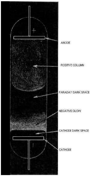
The figure above shows the main regions that may be present in a glow discharge. Regions described as “glows” emit significant light; regions labeled as “dark spaces” do not. As the discharge becomes more extended (i.e., stretched horizontally in the geometry of the figure), the positive column may become striated. That is, alternating dark and bright regions may form. Relatedly, compressing the discharge horizontally will result in fewer regions. The positive column will be compressed while the negative glow will remain the same size, and, with small enough gaps, the positive column will disappear altogether. In an analytical glow discharge, the discharge is primarily a negative glow with dark region above and below it.
Basic Glow Discharge Structure
The voltage current characteristic of a glow discharge is highly non-linear, as are many plasma phenomenon, and ordinary linear physics can not be applied to explain their struture. For a basic DC glow discharge, three main regions can be distinguished from each other, dark discharge, glow dicharge and arc discharge.
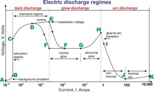
The above figure is a typical V/I plot of a glow discharge. The main characteristics of the discharge such as the breakdown voltage, the voltage current characteristic and the structure of the discharge depend on the geometry of the electrodes, the gas used, the pressure and the electrode material.[2]
Dark Discharge (dark current mode)
The regime between A and E on the voltage-current characteristic is termed a dark discharge because, except for corona discharges and the breakdown itself, the discharge remains invisible to the eye.
- A – B During the background ionization stage of the process the electric field applied along the axis of the discharge tube sweeps out the ions and electrons created by ionization from background radiation. Background radiation from cosmic rays, radioactive minerals, or other sources, produces a constant and measurable degree of ionization in air at atmospheric pressure. The ions and electrons migrate to the electrodes in the applied electric field producing a weak electric current. Increasing voltage sweeps out an increasing fraction of these ions and electrons.
- B – C If the voltage between the electrodes is increased far enough, eventually all the available electrons and ions are swept away, and the current saturates. In the saturation region, the current remain constant while the voltage is increased. This current depends linearly on the radiation source strength, a regime useful in some radiation counters.
- C – E If the voltage across the low pressure discharge tube is increased beyond point C, the current will rise exponentially. The electric field is now high enough so the electrons initially present in the gas can acquire enough energy before reaching the anode to ionize a neutral atom. As the electric field becomes even stronger, the secondary electron may also ionize another neutral atom leading to an avalanche of electron and ion production. The region of exponentially increasing current is called the Townsend discharge.
- D – E Corona discharges occur in Townsend dark discharges in regions of high electric field near sharp points, edges, or wires in gases prior to electrical breakdown. If the coronal cuurents are high enough, corona discharges can be technically “glow discharges”, visible to the eye. For low currents, the entire corona is dark, as appropriate for the dark discharges. Related phenomena include the silent electrical discharge, an inaudible form of filamentary discharge, and the brush discharge, a luminous discharge in a non-uniform electric field where many corona discharges are active at the same time and form streamers through the gas.
- E Electrical breakdown occurs in Townsend regime with the addition of secondary electrons emitted from the cathode due to ion or photon impact. At the breakdown, or sparking potential VB, the current might increase by a factor of 104 to 108, and is usually limited only by the internal resistance of the power supply connected between the plates. If the internal resistance of the power supply is very high, the discharge tube cannot draw enough current to break down the gas, and the tube will remain in the corona regime with small corona points or brush discharges being evident on the electrodes. If the internal resistance of the power supply is relatively low, then the gas will break down at the voltage VB, and move into the normal glow discharge regime. The breakdown voltage for a particular gas and electrode material depends on the product of the pressure and the distance between the electrodes, pd, as expressed in Paschen’s law (1889).
Glow Discharge (normal glow mode)
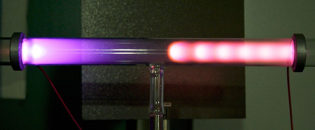
The glow discharge regime owes its name to the fact that the plasma is luminous. The gas glows because the electron energy and number density are high enough to generate visible light by excitation collisions. The applications of glow discharge include fluorescent lights, dc parallelplate plasma reactors, “magnetron” discharges used for depositing thin films, and electrobombardment plasma sources.
- F – G After a discontinuous transition from E to F, the gas enters the normal glow region, in which the voltage is almost independent of the current over several orders of magnitude in the discharge current. The electrode current density is independent of the total current in this regime. This means that the plasma is in contact with only a small part of the cathode surface at low currents. As the current is increased from F to G, the fraction of the cathode occupied by the plasma increases, until plasma covers the entire cathode surface at point G.
- G – H In the abnormal glow regime above point G, the voltage increases significantly with the increasing total current in order to force the cathode current density above its natural value and provide the desired current. Starting at point G and moving to the left, a form of hysteresis is observed in the voltage-current characteristic. The discharge maintains itself at considerably lower currents and current densities than at point F and only then makes a transition back to Townsend regime.
Arc Discharges (arc mode)
- H – K At point H, the electrodes become sufficiently hot that the cathode emits electrons thermionically. If the DC power supply has a sufficiently low internal resistance, the discharge will undergo a glow-to-arc transition, H-I. The arc regime, from I through K is one where the discharge voltage decreases as the current increases, until large currents are achieved at point J, and after that the voltage increases slowly as the current increases.
Fusion in Glow Discharges
The properties of glow discharges have been suggested as an ideal way to create fusion energy, and some fusion techniques have been developed to utilise the properties and various modes of operation of glow discharges as a vital component in this process. The most notable of which is Inertial-Electrostatic Confinement Fusion (IECF). In this process, fuel ions are trapped with purely electrostatic fields in a convergent geometry, as opposed to magnetic confinement and other similar more popular methods. The inventor of this concept was U.S. scientist Philo Farnsworth, who came up with the idea in the 1950’s. Other variations on this include the Polywell concept,[3] the Penning trap,[4] the Perodically Oscillating Plasma Sphere (POPS),[5] and multi-electrode (#electrodes >2) devices.[6] All of these devices include some feature that make them more complex than the simple two electrode glow discharge devices, often with the intention of circumventing some of the loss mechanisms associated with IECF devices.
Inertial-Electrostatic Confinement Fusion (IECF)
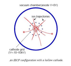
the properties of the glow discharge.[8] It basically consists of a transparent hollow cathode at the center of a spherical vacuum chamber (serves as an anode), usually filled with a D2 fuel gas, and a glow discharge takes place between them. The resulting high-energy ions interact with the background gas (beam-background collisions) and themselves (beam-beam collisions) in a small volume around the center spot, resulting in a high rate of fusion reactions. The result is a neutron generator producing neutrons on the order of 106-108 neutrons per second. In devices using even higher injection rates, the injected ions may provide a deep self-generated potential well that confines trapped beam ions, creating even higher reaction rates. The device may be modified by using a fill gas mixture of deuterium and helium-3 to be a source of protons as well as neutrons. IECF also has promising applications for landmine detection. [7]
Modes of operation associated with IECF
The glow discharge in IECF machines can be categorized according to four distinctive discharge modes. These are the Central Glow mode, the Star mode, the Halo mode, and the Jet mode. The names are descriptive of the visual appearances of the light emitted from the discharges. Each mode is associated with a different potential well structure, hence neutron production rate, for given operating parameters. Each requires a unique combination of operating parameters, i.e, voltage, current, pressure and grid parameters.[9]
- Central Glow mode In the Central Glow mode, a ball-shaped glow is produced in the center of the sphere. To produce it, an ion source such as ion gun or an ion source grid or an electron emitting cathode can be used. In the cathode, the grid is made as spherical as possible, composed of many fine grid wires with many openings to obtain a large geometric transparency and a reasonably uniform and spherically symmetric flow of ions. In such operation, the grid transparency is a key parameter: since ions flow almost uniformly through the grid, a fraction of the current is intercepted and lost to the grid wires. The higher the geometric transparency of the grid, the lower the loss fraction of ions—increasing the ion recirculation rate. The reaction rate in the center spot is correspondingly increased, and the heating and sputtering of the grid by ion bombardment is reduced. Thus, developing and optimizing such grid designs were the primary goals of earlier workers in the field. For similar operating voltages and currents, this mode gives only about one-third of the neutron output per unit power input compared to the Star mode.[9]
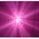
- Star Mode: To create the Star mode, a grid is constructed such that the grid opening diameter is a significant fraction of the major circumference of the grid. This causes a local depression of the potential surface. (This depression is to be avoided to create the Central Glow mode.) This depression in turn causes the ion flow to become focused, forming the characteristic radial ion beams or “spokes” of the Star mode. In planar discharges, consideration of the sheath in only 1 dimension is possible, but the discrete nature of the cathode grid of a glow discharge in a spherical shape results in a complicated 3D potential structure. This results in the cathode acting as an effective charged particle lens due to the curvature of the field between the individual cathode grid wires. This means that we do not have a homogenous flow of particles between electrodes, but rather a heterogeneous flow structure of plasma “spokes” transporting particles between the electrodes. The spokes are also luminous as indicated in Fig. 1. Star Mode typically occurs at pressures of ~ 1 to 25mTorr.[10]
- Halo Mode: This is initiated in the same manner as the Star mode, and is similar in many respects, but usually at lower pressures, and hence, higher cathode voltages. The transition to the Halo mode is accomplished by enlarging one or more of the grid openings (i.e., physically removing the wire section separating adjacent openings). This causes a flow of electrons out of the center volume (electron jet) under which circumstance the Halo mode develops. Then a strong jet of electrons is observed to flow through the enlarged opening(s). Up to six jets have been created on opposite faces of the grid in question. The jet in turn creates new ions by collisional ionization of the background neutrals. The resulting ion and electron flows causes a complete redistribution of space charge, thus forming a new potential well structure characterized by a bright central glow and an outer glowing halo region. A bright white, spherical halo is formed concentric to the cathode grid with a bright spot at the center. Accordingly, this operational mode has been termed the Halo mode. The Halo has always been accompanied by the electron jet, noted above, which is believed to be a fundamental characteristic of the mode. The Halo mode generally offers a factor of 1.5 to 3 times higher rates of neutron emission per unit input power than does the Star mode.[9]
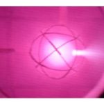
- Jet Mode: As the pressure is increased above “Star Mode” operating regimes, the discharge is visibly more uniform with the exception of radial variance and is accompanied by an electron jet through a particular grid hole of the cathode grid.[11] See Fig. 2. For this reason, this mode is referred to as “Jet Mode”. Despite the visual uniformity, a heterogeneous electron flow structure still exists between the anode and cathode in “Jet Mode”.[10]
Notes
- ↑ Thornhill, W The Z-Pinch Morphology of Supernova 1987A and Electric Stars (2007) IEEE Transactions on Plasma Science, vol. 35, issue 4, pp. 832-844 PEER REVIEWED
- ↑ Structure of a Glow Discharge Princeton Plasma Physics Laboratory
- ↑ N.A. Krall, The Polywell™: A Spherically Convergent Ion Focus Concept Fus. Tech., vol. 22, pp. 42-49, Aug. 1992 PEER REVIEWED
- ↑ Barnes, D. C.; Nebel, R. A.; Turner, Leaf Production and application of dense Penning trap plasmas (1993) Physics of Fluids B: Plasma Physics, Volume 5, Issue 10, October 1993, pp.3651-3660 PEER REVIEWED
- ↑ Park, J. Nebel, et al. Periodically oscillating plasma sphere (2005) Physics of Plasmas, Volume 12, Issue 5, pp. 056315-056315-6 Los Alamos National LaboratoryPEER REVIEWED
- ↑ T. J. McGuire; Improved confinement in inertial electrostatic confinement for fusion space power reactors (2005) Journal of propulsion and power, Volume 21 PEER REVIEWED
- ↑ 7.0 7.1 Yoshikawa, K, et al, Research and Development of a Compact Fusion Neutron Source for Humanitarian Landmine Detection (2007) IEEE Nuclear Science Symposium Conference Record, 2007. NSS ’07. PEER REVIEWEDFULL TEXT
- ↑ Nadler, J.H.; Knoll, D.A. Assessment of existing IEC models and a proposed new approach formodeling gridded systems (1995) Fusion Engineering, 16th IEEE/NPSS Symposium Volume 2, Issue, 30, Page(s):1472 – 1475 vol.2 PEER REVIEWED
- ↑ 9.0 9.1 9.2 MILEY, George, H. GU, Yibin, et al. Inertial-Electrostatic Confinement Particle Generator (1995) PATENT.
International Application No. PCT/US1995/005185 FULL TEXT - ↑ 10.0 10.1 10.2 10.3 Ryan Meyer, Dr. Mark Prelas, Dr. Sudarshan Loyalka INERTIAL ELECTROSTATIC CONFINEMENT: THEORETICAL AND EXPERIMENTAL STUDIES OF SPHERICAL DEVICES (2007) Dissertation presented at the University of Missouri-Columbia. 236 Pages. FULL TEXT
- ↑ MILEY, George, H. et al, Plasma Jet Source Using An Inertial Electrostatic Confinement Discharge Plasma (1998) Device Patent. International Application No. PCT/US1997/019306 FULL TEXT